Table of Contents
This page documents my work on building a robot arm. At a glance this project covers:
- Deriving the inverse kinematics equations for a 5DOF robot arm, and implementing them in simulation and on hardware, handling various edge cases and hardware limitations
- Writing a simulator in matplotlib for not only the 5DOF arm but also a 6DOF arm
- Designing the arm in FreeCAD and 3D printing it
- Using a Raspberry Pi Pico W to control the servo motors and communicate with the web server
Repositories: Robot Arm, Simulation
This project can be split into seven parts:
- The kinematics
- The simulation
- The CAD
- The electronics
- The Pico program
- The server program
- The web interface
Some terminology
I refer to ’links’ and ‘joints’ throughout this article - joints are the servo motors (i.e., the things that make the parts of the arm rotate (although, more generally, joints do not have to be rotational)), and links are the things that hold the joints together.
The kinematics
I learnt forward and inverse kinematics by reading chapters 2, 3, and 5 of Robot Modelling and Control by Spong, Hutchinson, and Vidyasagar. It’s a pretty good book, but doesn’t give away all the answers. The book focuses on the case of a 6DOF robot arm with a spherical wrist, which is one of the robots I added to my simulation, but the 5DOF case is slightly different. My 5DOF robot does not have the first joint in the spherical wrist, which essentially means the wrist cannot yaw independently of the base of the robot. This limits the orientations of the end-effector, but not their positions, and for many tasks, this is fine. It meant that I had to calculate the yaw as a function of the base angle, and then use the 6DOF solution. Various other edge cases and limitations, such as the fact that my robot’s motors only rotate between 0 and 180 degrees, rather than a full 360, had to be accounted for in the code.
The simulation
The simulation program uses matplotlib to plot lines representing the links of the robot arm, as well as the coordinate frames of each joint. This was my first time writing a non-trivial object-oriented program, and I learnt lots about classes in Python and structuring code in general. It makes use of the model-view-controller pattern, which keeps the code nice and organised.
The simulation inclues options for simulating a 3DOF elbow manipulator, which forms the basis for the 5DOF and 6DOF manipulators, as well as the two more involved options. Below are videos of the 5 and 6DOF manipulators. You can see that the difference between the two is that the wrist cannot yaw independently of the “shoulder” of the arm in the 5DOF case, which as you can see in the video, results in the 5DOF arm being more limited in its choice of orientation for a given point (the yaw is coupled to the angle of the shoulder).

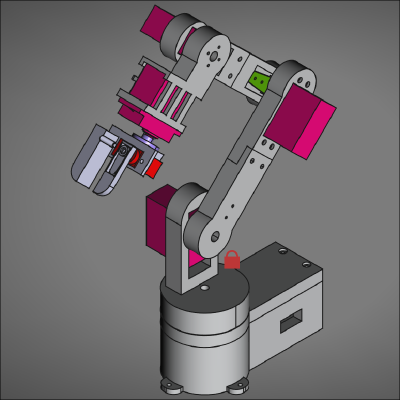
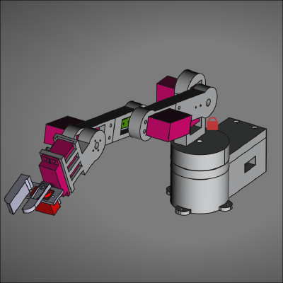
The CAD
The robot was designed using FreeCAD. I designed all the parts myself. While the robot works, there are a lot of things I would have done differently if I were to start over:
- Most importantly, the robot is very unstable. This was my first CAD design where knowledge of mechanical design techniques (which I possess very little of) played an important role. If I was to start over, I would like to buy some better motors, ideally ones where you can connect both sides of the motor to a joint. Since I wanted this first project to be cheap, this was sort of a necessary drawback.
- The shoulder joint was designed to just slot into the base, this means there is a lot of wiggle, so the positions taken by the model are often off by a couple of millimetres.
- The claw placement currently does not follow the Denavitt-Hartenberg convention. This was not a problem, until I implemented inverse kinematics. What it means in practice is that the claw position is always slightly off from the desired position. For this reason, there aren’t any videos of the robot actually picking anything up in this article.
The electronics
The electronics in this project are very simple. The robot is controlled by a Raspberry Pi Pico W which connects to a PCA9685 servo driver board via I2C. The four MG99R servos and the one MG90s servo motor are connected to and controlled by this servo driver. The Pico receives joint angles from my PC via USB, then sends the angles to the servo driver, which then moves the servos. All the wiring lives on a breadboard.
The Pico program
The Pico code is written in Micropython. Originally, both cores on the Pico were utilised, courtesy of the _thread library. Servo control was handled by core0 and networking (for communication with the server (my PC)) was handled by core1. Servo control was implemented as a callback that activated every time servo angles were sent from the server. Long polling was used: The Pico sent a HTTP GET request for angles to the server, and the server responds when they are updated. Unfortunately, this wasn’t the most reliable form of communication, and it included lots of overhead. I wanted to simplify the process using Websockets rather than long polling, but couldn’t find any decent libraries that allowed to Pico to use Websockets while acting as a client, and my networking knowledge is limited to the point where I didn’t want to write my own.
My solution came in the form of an even further simplification. Since my robot and server are always next to each other anyway, I simply chose to send servo angles from my PC to the Pico over USB, using pyserial. This made the code on the Pico much simpler, and threading was no longer needed. Now the Pico simply waits for data to be received, then moves the servos accordingly via Kevin McAleer’s micropython PCA9685 library.
The server
Originally, the server used the ThreadingHTTPServer class from the http.server library for communication with both the web interface and the Pico. As mentioned in the last section, the Pico now receives data via USB, and with this change I also moved to using the Microdot library for communication with the web interface. This makes the code a lot more readable by hiding away all the HTTP boilerplate.
The server receives data from the web server: either angles or pose. Angles are immediately sent to the Pico, whereas pose data is first passed to the inverse kinematics method of the robot arm object, different arm configurations (e.g., elbow up vs elbow down) are checked for validity, and the resulting angles are sent over to the Pico, which then moves the servos.
The web interface
The front end of the web interface is an exceedingly basic HTML file, containing only 6 sliders (for angle and claw control), some text boxes to specify position and orientation and a few buttons to submit data. Maybe I’ll add some CSS in the future.
Next steps
As I mentioned in the CAD section, this robot, while functional, leaves a lot of room for improvement. This is of no surprise, since this was my first time building a robot, and I was bound to make mistakes. Nevertheless, I am due an upgrade. Over the course of this project, I most enjoyed working on the mathematics and programming side of things, as opposed to the CAD design and electronics. With that in mind, I have decided to build a LeRobot SO-101 arm for the next stage of this project (and some future projects using reinforcement learning hopefully).
The next stage is the addition of a camera to the workspace, which will run an object detection algorithm written in PyTorch - I’m currently learning about convolutional neural networks. I can then use my knowledge of rigid motions (learnt from Robot Modelling and Control) to determine the position of the objects detected in the camera frame to get their coordinates in the base frame, and move the robot accordingly.